
Your shopping cart is empty!
Categories
Bestsellers

Live Chat
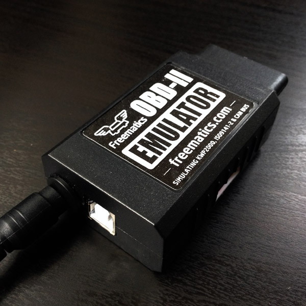
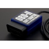
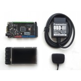
Freematics OBD-II Emulator MK2


Price: US$395.00
Qty:
- OR -
Add to Wish List
Add to Compare
Add to Compare
Freematics OBD-II Emulator MK2 is a powerful and compact emulator that replicates a real vehicle’s OBD‑II port for development, testing, and diagnostics—on the bench or in the field.
Key Highlights
-
Realistic OBD‑II Simulation: Emulates a standard 16‑pin female OBD‑II port, supporting CAN (11/29‑bit at 250/500 kbps), ISO9141‑2, KWP2000, and optional J1850 PWM/VPW
-
Comprehensive Protocol & Diagnostic Support: Responds to Mode 01 PIDs (0100–0163), DTCs (Modes 03/07/0A, up to 6 active), readiness monitors, calibration ID/numbers, and VIN (Mode 09)
-
Flexible Control Interfaces: Configure via USB with PC GUI, wireless BLE control through mobile app, or AT‐command via TTL serial
-
Powered & Programmable: Passes through 12 / 24 V up to 3 A to feed connected devices; firmware can be upgraded via USB
Ideal Applications
-
Software, tool, and hardware developers needing controlled OBD‑II emulation
-
Testing and validation teams replicating fault conditions or vehicle states
-
Use with legacy or non‑OBD equipped vehicles to test existing diagnostic tools
Supported Vehicle Protocols
- CAN/ISO15765 500Kbps/11bit
- CAN/ISO15765 250Kbps/11bit
- CAN/ISO15765 500Kbps/29bit
- CAN/ISO15765 250Kbps/29bit
- ISO9141-2
- KWP2000/ISO14230 Fast
- KWP2000/ISO14230 5Kbps
- J1850 VPW (optional)
- J1850 PWM (optional)
Please note the emulator does not actively generate CAN signals without presence of a plugged in OBD device.
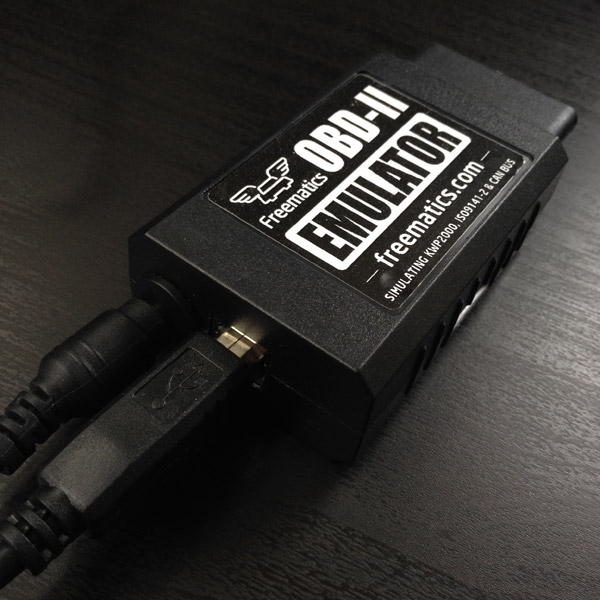
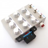
Hardware Interfaces
The emulator has following sockets on its enclosure:
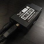
- 16-pin female OBD-II port (powered)
- DC input jack
- USB port
- I/O socket
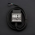
The I/O socket (6-pin socket at the side or 4-pin socket at the end) provides an interface for serial TTL connection as well as DC power supply. This makes it possible for a micro-controller like Arduino to manipulate the emulator’s states and data in real-time via AT command-set. For 6-pin socket (legacy), the pin definitions are Tx, Rx, GND, 3.3V, 5V, 12V (left-to-right). For 4-pin socket, the pin definitions are Tx, Rx, GND, 5V (left-to-right).
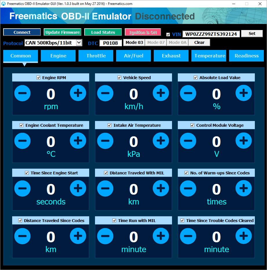
PC GUI Software
An open-source GUI software is developed for configuring and controlling the emulator. The Windows binary can be downloaded here. Simply extract the downloaded compressed file and run FreematicsEmulator.exe to launch the GUI.

To start using the emulator with PC GUI, follow these steps:
1. Connect DC power adapter to the emulator
The emulator requires a DC power supply for powering itself as well as passing through to connected OBD device. If the connected device requires power surge over 1A, a power source with higher rating may be needed. The DC input socket is located beside the USB port.
2. Plug in USB cable and connect to PC
If not previously installed, a USB driver is needed and can be downloaded here.
3. Open Freematics OBD-II Emulator GUI software and connect with the emulator
Run FreematicsEmulator.exe to launch the GUI software. Once the GUI is loaded, it will automatically attempt to connect with the emulator. Once connected, the Connect button will turn into Disconnect.
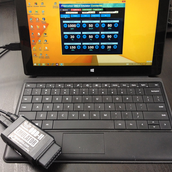
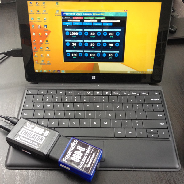
4. Plug in your OBD-II device (with OBD-II male connector) into emulator’s OBD-II female port
Now plug in your OBD-II device and it should work as if plugged in the OBD-II port of a real car. You can use the GUI to change the value of OBD-II PIDs, state of readiness monitors, diagnostic trouble code (DTC) and VIN.
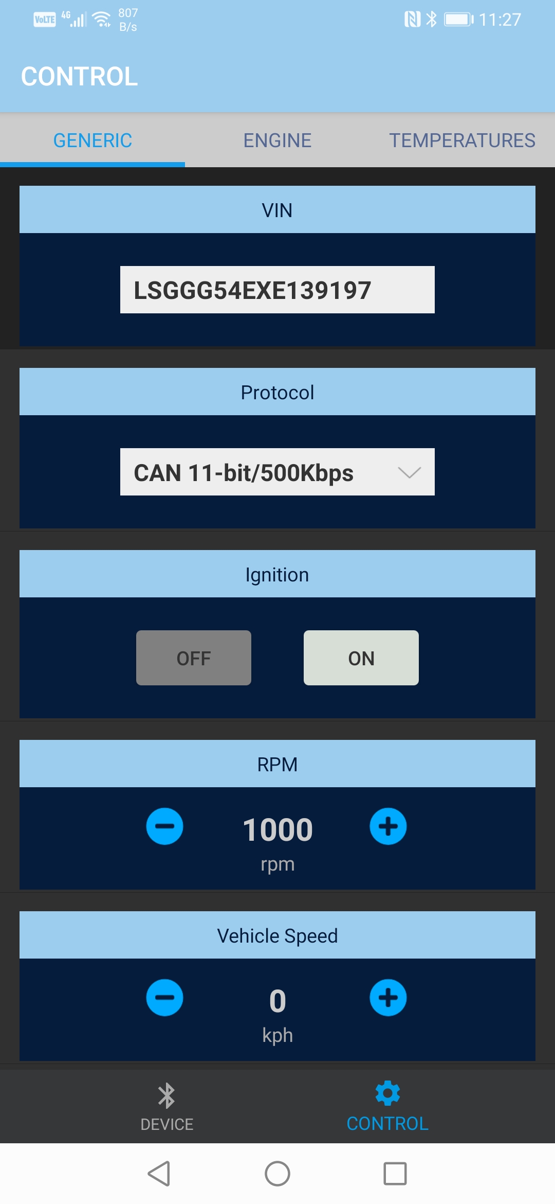
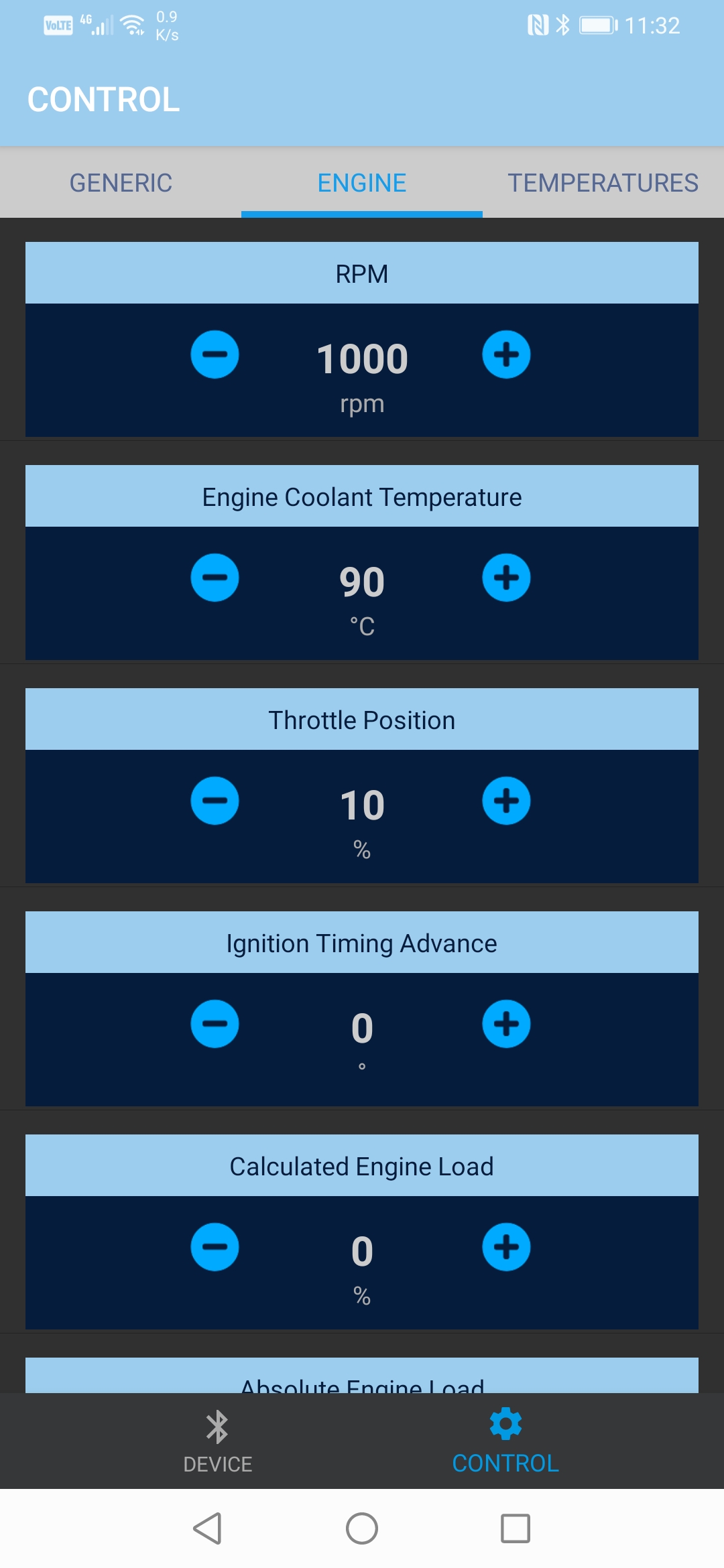
Android App
Freematics OBD-II Emulator MK2 can be remotely controlled via BLE (Bluetooth Low Energy) by Freematics Controller App (click here to download the APK). Only a sub-set of PC GUI features is available from the App.
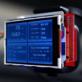
Advanced Features
-
Continuous Mode: Although primarily request/respond, can be scripted to simulate periodic live data streams using AT commands or custom scripts via serial/USB.
-
Extendable Setup: Connect sensors or microcontrollers (Arduino, PIC, ESP32) to the TTL port for automated data injection or live simulation.
Serial Control Interface
Freematics OBD-II Emulator MK2 is configured and controlled by a AT Command-Set which the GUI software and Android App are both implemented with.
Power Supply
The emulator can pass-through DC power up to 30V/3A. A power adapter rated 12V/1A with 5.5/2.1mm connector (center positive) can be supplied. It is recommended however to use a DC power supply with higher rating in case any more power consuming OBD device will be plugged in. A voltage adjustable power source is handy for mimicking voltage change in real cars. Please note the pin 16 (battery voltage pin) on emulator’s OBD port is not fused.

Shipping List
- Freematics OBD-II Emulator MK2 x 1
- USB Cable x 1
- DC Power Adapter (5.5/2.1mm) x 1
Links
Powered By OpenCart
Freematics Online Store © 2026
Freematics Online Store © 2026