
Your shopping cart is empty!
Categories
Bestsellers
Live Chat
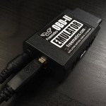
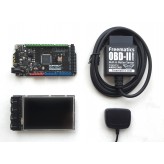
Freematics OBD-II UART Adapter V2.1 (for Arduino)
")
")
")
")
Price: US$59.90
Qty:
- OR -
Add to Wish List
Add to Compare
Add to Compare
This product works as a data bridge between a car’s OBD port and Arduino (or similar hardware) with a dedicated open-source library provided. It provides high-speed OBD-II data access and integrates 9-DOF motion sensor with built-in sensor fusion algorithm. The adapter is powered directly from OBD port and outputs regulated 5V voltage for powering attached devices.
Features
- Access to all standard OBD-II PIDs with ELM327 AT command-set
- Reading and clearing vehicle diagnostic trouble codes (engine & powertrain only)
- CAN bus sniffing
- Car battery voltage measurement
- Motion sensing with MPU-9250 9-DOF motion sensor
- Orientation measurement with built-in quaternion sensor fusion algorithm
- Power supply (5V/2.1A)
- Serial UART compatible with both 3.3V and 5V micro-controllers
- Micro USB for computer/tablet connection
- Arduino library and example sketches available
Compatibility
The adapter plugs into the OBD port usually located under the steering column or slightly to the left of it. To check if your vehicle is OBD-II certified, open your hood and find the sticker that looks like this:
Vehicles using following vehicle protocols are supported.
- CAN 500Kbps/29bit
- CAN 500Kbps/11bit
- CAN 250Kbps/29bit
- CAN 250Kbps/11bit
- KWP2000 Fast
- KWP2000 5Kbps
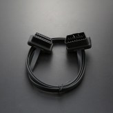
Connectors
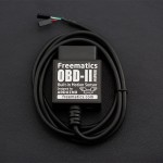
The adapter stays plugged into the OBD port usually located under the steering column or slightly to the left of it. A unpluggable cable comes out from the adapter and splits into one 4-pin connector two 2-pin connectors, including power lines (VCC/GND) and data lines (Rx/Tx). They can be connected to Arduino with onboard breakout pins or breakout shield. Your Arduino device will look tidy in car with only one cable.
Power Connector (2-pin 2.54 Dupont connector)
- Red: VCC (connecting to Arduino’s VCC)
- Black: GND (connecting to Arduino’s GND)
Serial UART Data Connector (2-pin 2.54 Dupont connector)
- White: Rx (connected to Arduino’s serial Tx)
- Green: Tx (connected to Arduino’s serial Rx)
Note: Arduino UNO or Nano only has one hardware serial which is also used by USB serial. Avoid using serial output if the adapter is connected to hardware serial. Arduino Leonardo, Mega, Due do not have this limit.
USB Port
- For connection with computer or tablet via micro USB cable
- Allows power output (5V/2A)
Extended AT Command Set
We have extended standard ELM327 command set for following purposes:
- Reading built-in MEMS motion sensor data
- Reading orientation result from sensor fusion computation
- Data bus specific controls
- CAN bus sniffing
Motion Sensor Access
ATACL
- Function: reading accelerometer data
- Response format: X,Y,Z (in G)
ATGYRO
- Function: reading gyroscope data
- Response: X,Y,Z (in degree)
ATMAG
- Function: reading magnetometer data
- Response: X,Y,Z (in milli-Gauss)
ATTEMP
- Function: reading temperature data
- Response: temperature (raw) data
Quaternion Control and Orientation
ATQU0/ATQU1
- Function: disable/enable 9-DOF sensor fusion (disabled by default)
- Response: OK
ATORI
- Function: retrieving orientation parameters from 9-DOF sensor fusion
- Response: <yaw>,<pitch>,<roll> (in degree)
K-Line and ISO9141-2 Specific
ATSH <AA> <BB> <CC>
- Function: set header bytes
- Example: ATSH C1 33 F1
ATPTH <AA>
- Function: set initializing pulse time for (in hex, range of 0~255ms)
- Example: ATPTH 19 (set to 25ms)
ATPTA <BB>
- Function: set negative pulse duration before first data (in hex, range of 0~255ms)
- Example: ATPTA 32 (set to 50ms)
CAN Bus Specific (CAN bus sniffing)
CAN Bus Specific (CAN bus sniffing)
CAN Bus Specific
ATSH <ABC>
- Function: set CAN message header (on 11-bit CAN)
- Example: ATSH 7DF
ATSH <AA> <BB> <CC>
- Function: set lower 24 bits of CAN message header (on 29-bit CAN), higher 5 bits are set by ATCP command
- Example: ATSH DB 33 F1
ATCP <HH>
- Function: set CAN priority/higher 5 bits of header (on 29-bit CAN)
- Example: ATSH 18
ATCF <ABC> or <AA> <BB> <CC>
- Function: set CAN message header filter for CAN sniffing, <ABC> for CAN 11-bit, <AA> <BB> <CC> for CAN 29-bit
- Example: ATCF 7E8
ATCM <AA> <BB> <CC> <DD>
- Function: set CAN message filtering bit mask (32-bit)
- Example: ATCM FFFFFFFE (ignore the lowest bit when comparing with header filter number)
ATM1
- Start sniffing mode
ATM0
- Stop sniffing mode
Examples
Typical sniffing on 11-bit 500kbps CAN bus
- ATSP6
- ATCF 700
- ATCM FFFFFF00
- ATM1
Typical sniffing on 29-bit 500kbps CAN bus
- ATSP7
- ATCF 18DBF133
- ATCM FF000000
- ATM1
Arduino Library
A dedicated Arduino library is provided for easy access to all the features with any type of Arduino. Please note not all available AT commands are encapsulated into API.
Some commonly used APIs are like following:
- setBaudRate – set adapter serial baudrate
- readPID – read specified OBD-II PID and return parsed value
- clearDTC – clear diagnostic trouble code
- getVoltage – measure car battery voltage
- getVIN – retrieve Vehicle Identification Number
- getTemperature – get device temperature
- readAccel – read accelerometer X/Y/Z values
- memsInit – initialize motion sensor
- memsRead – read motion sensor data
- memsOrientation – retrieve computed orientation data
Here is an example code of a simplest engine RPM indicator, which uses the pin 13 LED (built in every Arduino board) to indicate whether the engine is above 3000 rpm.
#include <OBD2UART.h>

COBD obd;

void setup()
{
  // we'll use the debug LED as output
  pinMode(13, OUTPUT);
  // start serial communication
  obd.begin();
  // initiate OBD-II connection until success
  while (!obd.init());
}

void loop()
{
  int value;
  // save engine RPM in variable 'value', return true on success
  if (obd.readPID(PID_RPM, value)) {
    // light on LED on Arduino board when the RPM exceeds 3000
    digitalWrite(13, value > 3000 ? HIGH : LOW);
  }
}
More example sketches are here.
Some commonly used PIDs are defined in OBD library as following.
Engine
- PID_RPM – Engine RPM (rpm)
- PID_ENGINE_LOAD – Calculated engine load (%)
- PID_COOLANT_TEMP – Engine coolant temperature (°C)
- PID_ENGINE_LOAD – Calculated Engine load (%)
- PID_ABSOLUTE_ENGINE_LOAD – Absolute Engine load (%)
- PID_TIMING_ADVANCE – Ignition timing advance (°)
- PID_ENGINE_OIL_TEMP – Engine oil temperature (°C)
- PID_ENGINE_TORQUE_PERCENTAGE – Engine torque percentage (%)
- PID_ENGINE_REF_TORQUE – Engine reference torque (Nm)
Intake/Exhaust
- PID_INTAKE_TEMP – Intake temperature (°C)
- PID_INTAKE_PRESSURE – Intake manifold absolute pressure (kPa)
- PID_MAF_FLOW – MAF flow pressure (grams/s)
- PID_BAROMETRIC – Barometric pressure (kPa)
Speed/Time
- PID_SPEED – Vehicle speed (km/h)
- PID_RUNTIME – Engine running time (second)
- PID_DISTANCE – Vehicle running distance (km)
Driver
- PID_THROTTLE – Throttle position (%)
- PID_AMBIENT_TEMP – Ambient temperature (°C)
Electric Systems
- PID_CONTROL_MODULE_VOLTAGE – vehicle control module voltage (V)
- PID_HYBRID_BATTERY_PERCENTAGE – Hybrid battery pack remaining life (%)
Additional defines can be added to access all OBD-II PIDs which the car’s ECU provides.
Comparison
The following table lists the differences among all Freematics OBD-II adapter models.
| Features \ Models | OBD-II UART Adapter V1 | OBD-II UART Adapter V2 | OBD-II UART Adapter V2.1 |
|---|---|---|---|
| Connection Cable | Fixed | Fixed | Unpluggable |
| Additional Interface | N/A | micro USB | micro USB |
| Motion Sensor | N/A | 6-DOF MPU-6050 | 9-DOF MPU-9250 |
| Voltmeter | Yes | Yes | Yes |
| Max. Output Power | 2A | 2.1A | 2.1A |
| Standby Mode Power | 5mA | 6mA | 6mA |
FAQ
Q: What is this product used for?
A: The most straight-forward use of this product is for making Arduino possible to access vehicle data easily. The OBD-II data, together with other data from GPS or all kinds sensors, can be logged and stored on SD/TF card with Arduino and that makes an open-source vehicle data logger (check out the data logger kits). More extensively, many interesting interaction applications requiring car data can be made.
Q: How is the adapter powered?
A: The adapter gets power from the 12V DC output from the OBD-II port.
Q: Does my Arduino needs power from somewhere in the car?
A: The adapter provides regulated 5V output for powering Arduino and other devices, so no extra power cord is needed.
Q: Do I need a CAN bus shield to use with the adapter?
A: Definitely no. The adapter retrieves data from CAN bus, like a CAN bus shield does and convert the more complicated CAN bus interface to simple serial UART interface which Arduino and most embedded systems are easy to access. The data connection is provided by adapter’s data connector (Rx and Tx).
Q: How do I connect the adapter with my Arduino?
A: The adapter works with all models of Arduino with the dedicated Arduino library and is connected with Arduino by connecting adapter’s Tx to Arduino’s Rx (D0) and adapter’s Rx to Arduino’s Tx (D1). If you want to connect and disconnect the adapter with your Arduino effortlessly, it’s recommended to use a common I/O breakout shield or use an Arduino board with breakout pins for Rx/Tx/VCC/GND.
Q: Is the power provided by the adapter always available in car?
A: This depends on whether the OBD-II port of your car still has power after ignition is off. Actually it is so with most cars.
Q: What’s the maximum frequency of data polling?
A: The OBD-II PIDs are polled one after another. The time for a polling depends on the speed of car’s ECU computer and how busy the computer is in different status. With a typical modern car with CAN bus, the time can be as low as 10ms. In other word, up to 100 times of data polling can be done in one second.
Q: What if I have questions/obstacles about Arduino programming?
A: Sorry it is not our responsibility to provide any instructions on Arduino programming. There are abundant online guides and tutorials about Arduino programming for reference.
Q: What's the difference between product version and firmware version?
A: Freematics OBD-II UART Adapter V2 uses a firmware versioned 1.1. Freematics OBD-II UART Adapter V1 uses a firmware versioned 1.0.
Powered By OpenCart
Freematics Online Store © 2025
Freematics Online Store © 2025