The Parts
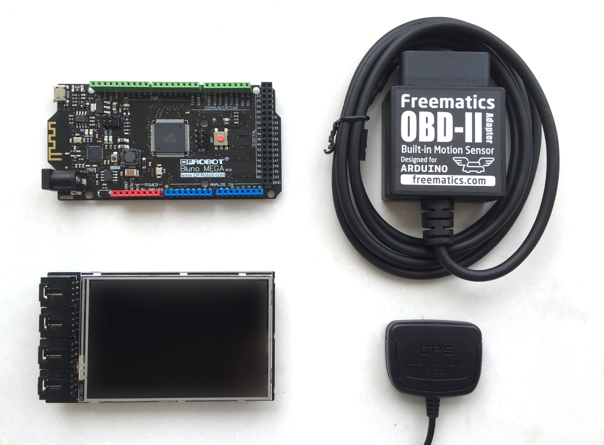
OBD-II Telematics Advanced Kit is an Arduino based hardware kit consisting of following parts (some are optional).
- Arduino MEGA compatible board (or ADK, Bluno MEGA)
- Telematics Shield for Arduino MEGA
- Freematics OBD-II Adapter for Arduino
- 10Hz GPS/GLONASS Receiver for Arduino (optional)
The kits come in separate parts and they can be assembled easily in these steps.
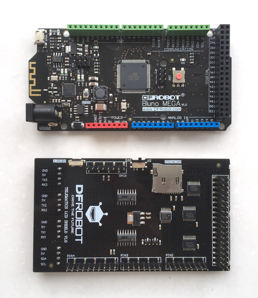
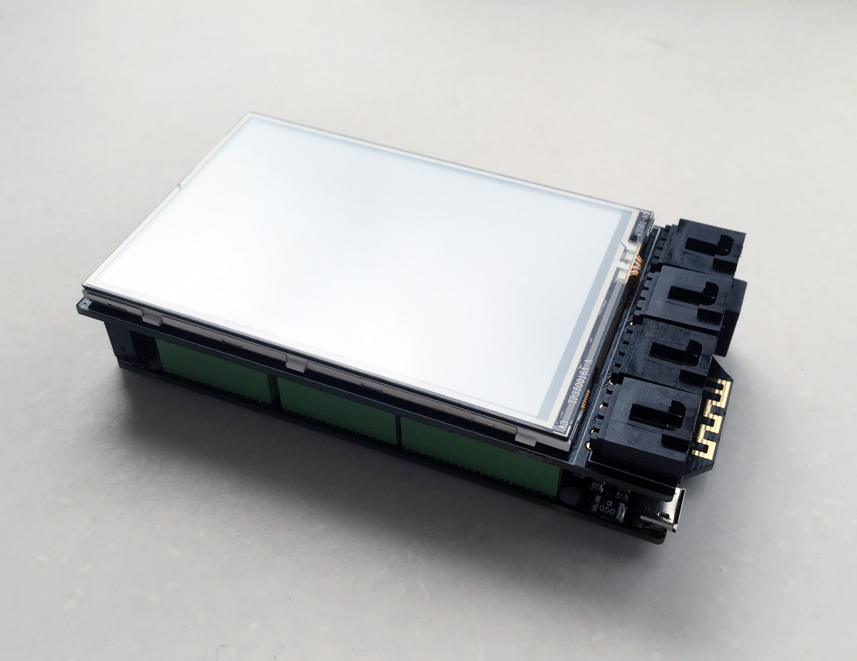
1. Attaching Telematics Shield to Arduino board
Telematics Shield is stacked on Arduino MEGA board (ADK or Bluno).
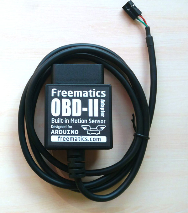
2. Connecting OBD-II Adapter to Telematics Shield
OBD-II Adapter has a 4-pin connector. The adapter coming with the kit has a label on the connector showing the socket to go into and the direction. For UART adapter, the connector goes into Serial1 socket. For I2C adapter, the connector goes into I2C socket. You don’t need to worry about the line definition.
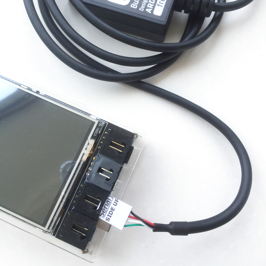
3. Connecting GPS receiver to Telematics Shield
The same is for the GPS receiver which also has a 4-pin connector. Follow the label and plug the connector into Serial2 socket.
The Sketch
The Arduino board needs a sketch (source code) to function. We have developed a fully functioning data logger sketch named MegaLoggerHD for this kit. If you know the basics about Arduino, everything is straight-forward. To upload a sketch to an Arduino board, do following steps.
1. Download and install Arduino IDE
There are two maintainers for Arduino IDE at the moment. You can choose your own preference. We recommend the one from here.
2. Download the sketch and libraries package
The latest revisions of sketch and libraries are hosted on Github. You can download a zip package (updated from time to time) containing sketch and library files from here.
3. Import Arduino libraries
To do this, copy all sub-folders from libraries folder into %HOMEPATH%\Documents\Arduino\libraries on your computer. Restart Arduino IDE to take effect.
4. Load and configure the sketch
Start Arduino IDE and load the sketch. On the top of Arduino IDE, you will see several tabs which correspond to each file in the sketch folder.
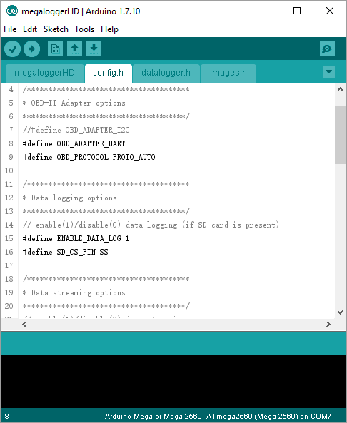
Go to the config.h tab and you can change common options include:
- OBD_MODEL – defines the model of OBD-II Adapter (UART or I2C)
- USE_GPS – whether to use GPS
- ENABLE_DATA_LOG – toggles data logging on microSD card
- ENABLE_DATA_OUT – toggles data streaming (to mobile devices via Bluetooth)
- STREAM_FORMAT – sets streaming data format (binary or text)
5. Upload sketch to Arduino board
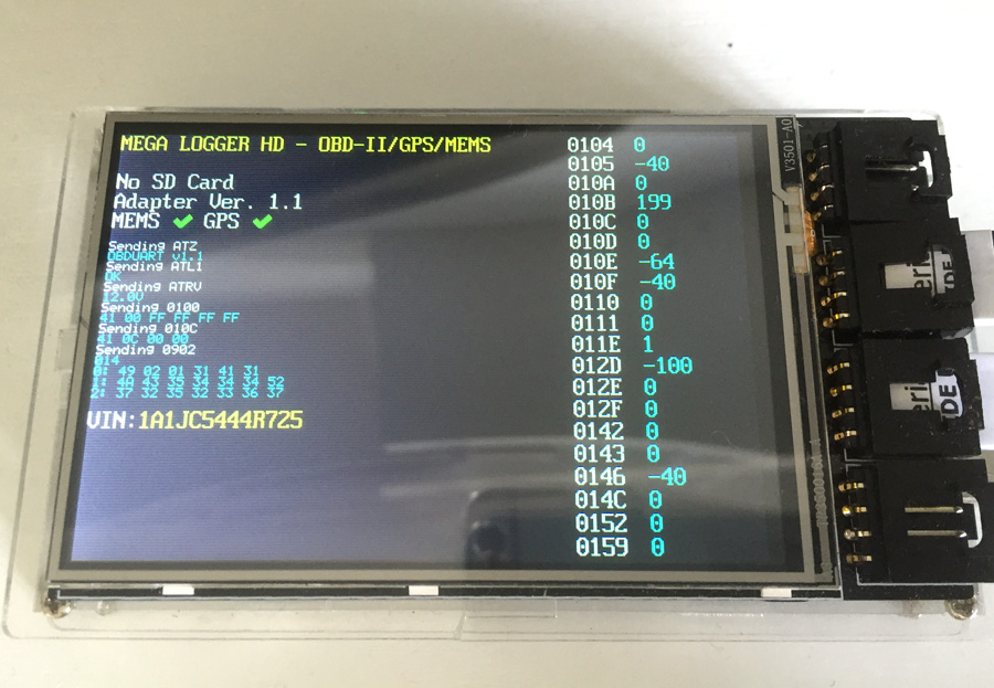
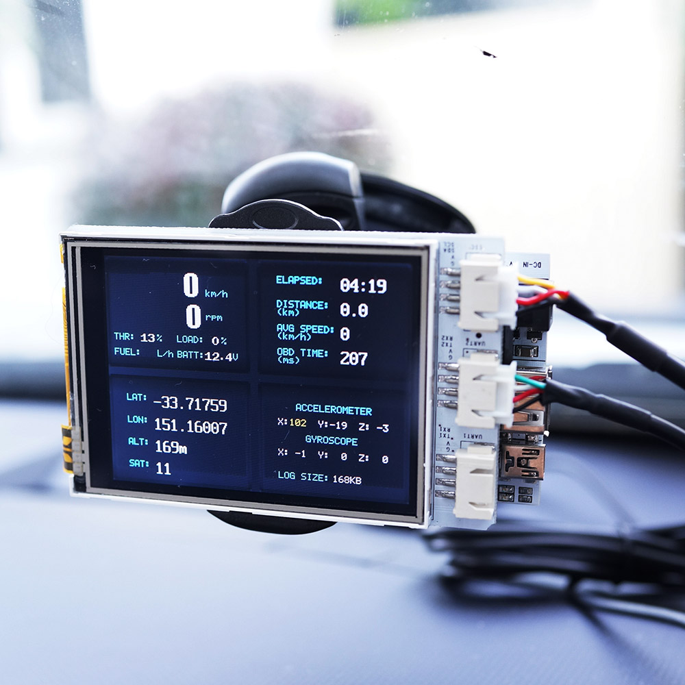
Connect the Arduino board to computer with USB cable. Choose serial port that appears after connecting the board. Change board type to Arduino MEGA 2560 (or 1280). Click Upload menu or button to perform the uploading. After completed, the LCD screen should begin to display.
Installing
The setup can be held on car’s dashboard top with car window mount coming with the kit. OBD-II adapter connects to the OBD-II port under the dashboard. The power for the whole setup also comes from OBD-II port.
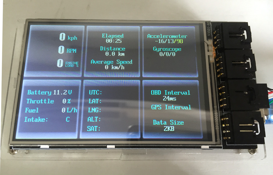
Data Logging
The kit provides complete data logging for OBD-II, GPS and motion sensor data. The data is stored on microSD card if present. Standard Arduino SD library used for accessing microSD card.
The data is logged in a simple CSV text format.Each line represents a record with time, data type and data value like this:
[Time Elapsed],[Data Type],[Data Value 1],[Data Value 2],[Data Value 3]
Time Elapsed is the time elapsed in milliseconds since previous data record. Data Type is the OBD-II PID which is defined in the OBD-II library (e.g. 0x10C is engine RPM). Here is an example data clip:
169,10D,0
171,111,12
170,143,21
165,10B,30
175,10C,705
169,10D,0
170,111,12
…
GPS data is defined as special PID which OBD-II standard does not use and are defined in datalogger.h file.
#define PID_GPS_LATITUDE 0xA
#define PID_GPS_LONGITUDE 0xB
#define PID_GPS_ALTITUDE 0xC
#define PID_GPS_SPEED 0xD
#define PID_GPS_HEADING 0xE
#define PID_GPS_SAT_COUNT 0xF
#define PID_GPS_TIME 0x10
#define PID_GPS_DATE 0x11
Motion sensor data is defined as following.
#define PID_ACC 0x20
#define PID_GYRO 0x21
They will have 3 data values for all 3-axis (X/Y/Z)
Data Streaming
Live data can be streamed to a mobile device via BLE module if Bluno (Arduino MEGA with BLE) is with your kit.