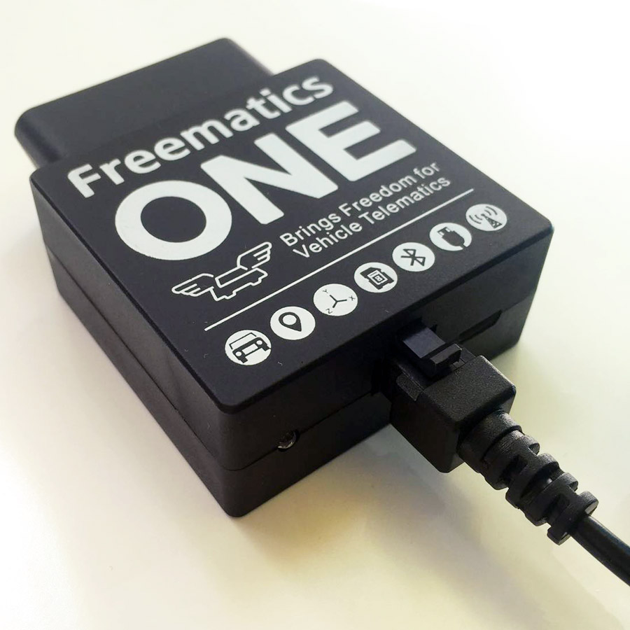
Freematics ONE is a piece of Arduino compatible open-source hardware in form of a OBD-II dongle. It runs compiled Arduino sketch and works accordingly as a vehicle telematics data collector/logger/transmitter after being plugged into car’s OBD-II port.
The main controller of Freematics ONE is ATmega328p which can be programmed exactly same as Arduino UNO from USB. Standard Arduino libraries can be used unmodified. Enhanced features are provided by a dedicated Arduino library. A STM32 co-processor is connected with ATmega328p working as peripherals data hub (for OBD, GPS and network module) and dealing with protocol decoding (CAN bus, KWP2000, NMEA). A MPU-9250 9-DOF motion sensor is connected with ATmega328p by I2C.
Interfaces and Components
Freematics ONE has following hardware interfaces and components outside and inside its enclosure:
- OBD-II Male Connector (16-pin)
- GPS Connector (4-pin)
- microSD card slot
- Micro SIM card slot (not used for units without cellular module)
- Micro USB Port
- LED Indicator
- xBee Socket (inside)
- BLE Module (inside)
OBD-II Male Connector
OBD-II male connector allows Freematics ONE to be plugged directly into OBD-II female port which is available in most modern cars. The OBD-II port provides connection between Freematics ONE and car’s ECU computer as well as power supply from car battery.
GPS Connector
GPS socket allows connection of external GPS receivers which come as an optional accessory. The 4-pin Molex connector is used for serial communication and providing power for GPS receiver. Normally OBD-II port sits underneath dashboard where no good GPS signal reception is available. External GPS receiver with a cable led out from Freematics ONE can be easily placed on dashboard or somewhere else for better signal reception.


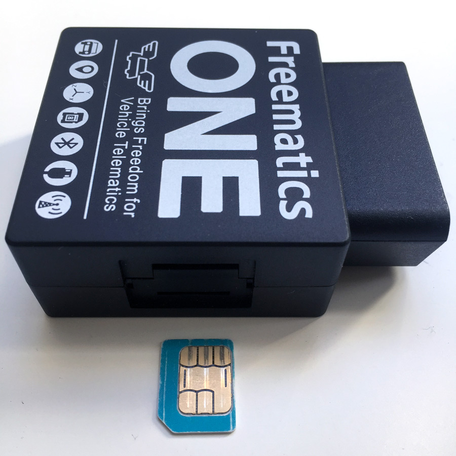
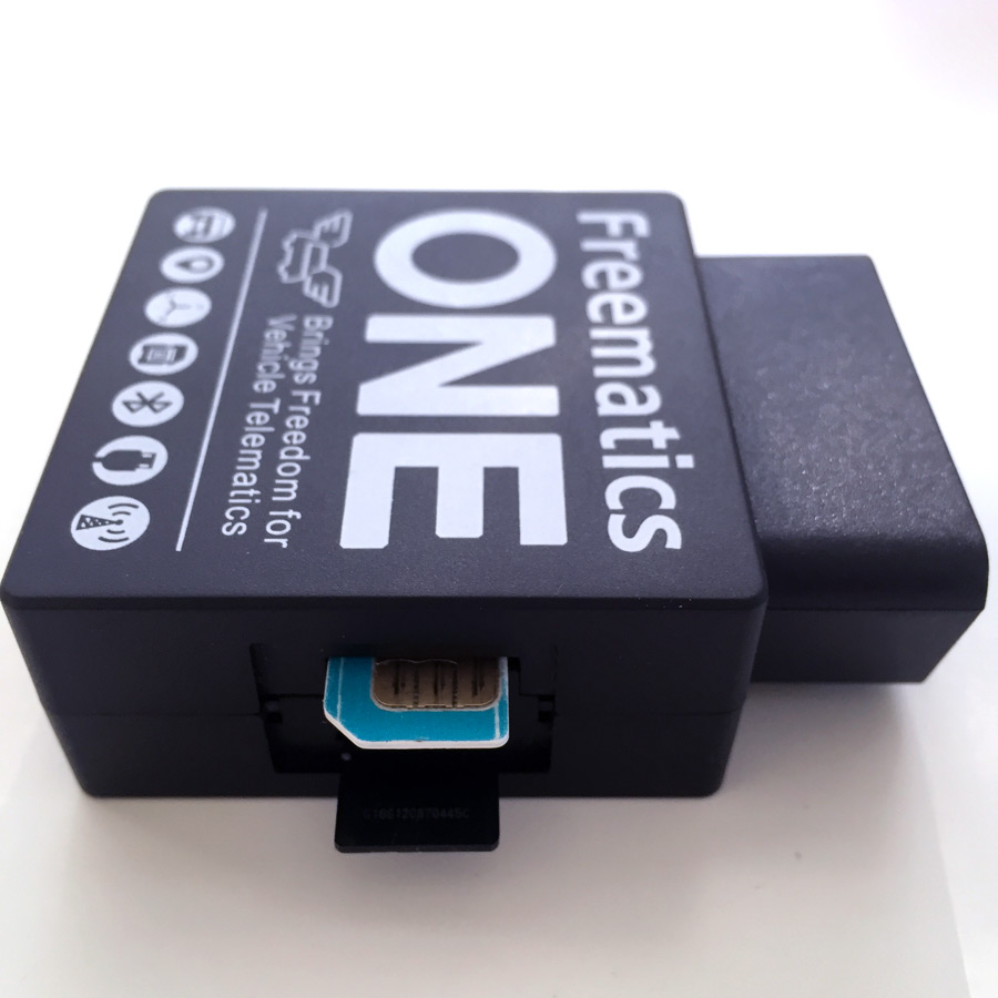
Card Slots
Freematics ONE has a microSD card slot and a micro SIM card slot under the plastic cover on one side of the enclosure. Both card seats are self-popping. Please avoid insert anything into SIM card slot if your Freematics ONE has no cellular module installed. Please make sure to insert microSD card and SIM card in the correct direction as shown below.

Micro USB Port
Micro USB port is used for Arduino sketch uploading as well as serial communication which is pretty same as for an Arduino board. The port can also be used for powering the device if no OBD-II connection is available.
LED indicator are on when powered on and flashing when there is USB or BLE communication.
xBee Socket
A 2x10pin xBee Socket is set on the PCB. It extends Freematics ONE with cellular network access.

BLE Module
A CC2541 BLE module with onboard antenna is attached on the back of PCB for both BLE communication with mobile devices like iPhone or iPad.
Compiling and Uploading
As an open-source hardware, the most important thing is being able to compile source code and upload to the unit.
1. Download and install Arduino IDE
If you don’t have it, download Arduino IDE from arduino.cc.
2. Download and import Arduino library
Download source code package for Freematics ONE from here. The package contains Arduino library for Freematics ONE and a bunch of example sketches which you can easily get started with. Having no idea about Arduino library and how to import one? Read this.

3. Download Arduino sketches for Freematics ONE and load one of them into Arduino IDE
You can either check out latest sketches from our Github. A couple of ready-to-go sketches for various purposes are available. Most of them are directly available from Arduino IDE examples menu if Freematics ONE library has been imported.
This sketch works as a data logger of OBD-II/GPS/MEMS data. Data is saved on inserted microSD card and streamed to mobile phone or tablet via BLE (in readable text). For the file format used for data logging, please refer to Freematics Data Logging Format.
This sketch demonstrates how OBD-II/GPS/MEMS data is collected and transmitted to remote server by UDP with SIM800L GSM/GPRS module. SIM800 AT command-set is used for GPRS communication. This sketch works with Freematics ONE with SIM800L module installed.
This sketch demonstrates how OBD-II/GPS/MEMS data is collected and transmitted to remote server by UDP with ESP8266 WIFI module ESP8266 command-set is used for WIFI communication. This sketch works with Freematics ONE with ESP8266 module installed.
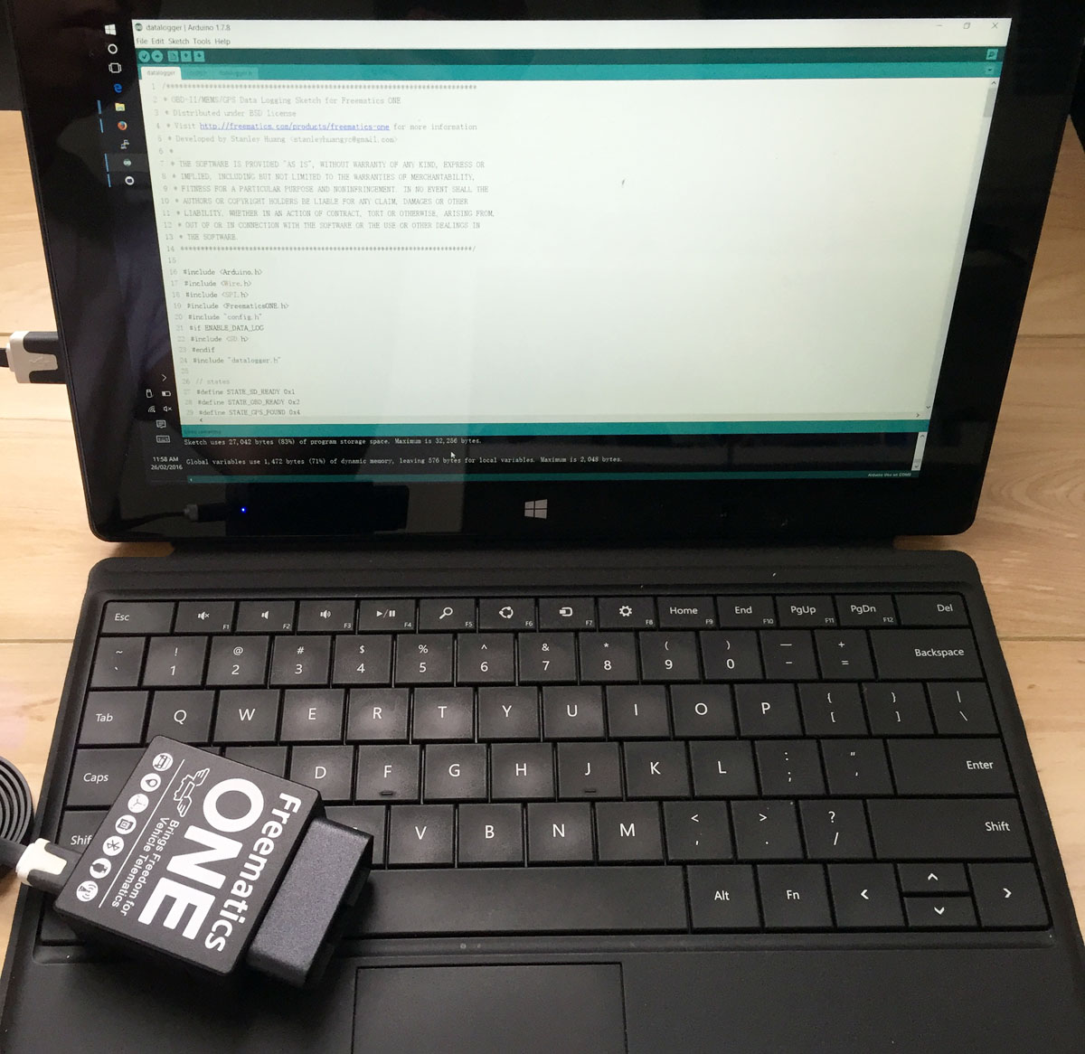
4. Connect Freematics ONE to computer by USB cable
Just like connecting an Arduino board, connect your Freematics ONE to your computer with supplied USB-to-microUSB cable.

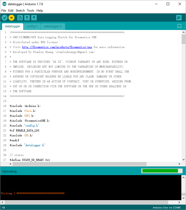
5. Compile and upload the sketch to Freematics ONE
In Arduino IDE, choose Arduino UNO as board and the serial port that Freematics ONE is on. Click upload button or menu to start uploading. Once completed, your Freematics ONE is ready to go with your car.