Shopping Cart
0 item(s) - US$0.00Freematics ONE+ Model B
Add to Compare
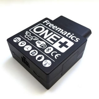
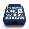
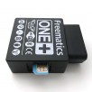
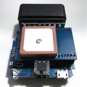
Freematics ONE+ Model B is a variant of Freematics ONE+ with integrated LTE cellular module and 10Hz GNSS module + antenna, still in form of a OBD dongle that directly plugs into a car’s OBD port.
Features
- Dual-core Arduino programmable SoC with built-in WiFi and Bluetooth
- Access to all standard OBD-II PIDs, DTC, VIN from vehicle ECU
- CAN bus data sniffing
- High update rate and accuracy GNSS geolocation
- G-force measurement and motion detection
- Car battery voltage reading
- Massive data storage (microSD up to 32GB)
- Real-time data transmission over WiFi and cellular network
- Configuring and monitoring from mobile device app via BLE
Hardware Facts
Specifications
- Espressif ESP32 with 16MB Flash, 8MB PSRAM, 32K RTC
- Built-in 802.11 b/g/n Wi-Fi and dual mode Bluetooth (classic and BLE)
- Integrated ICM-42627 motion sensor
- Integrated u-blox M10 GNSS module and antenna
- Integrated SIM7670 LTE CAT-1 cellular module
- Integrated buzzer
- Enclosure dimensions: 60x48x20mm
Physical Interfaces
- OBD-II male connector
- microUSB port
- microSD card slot
- SIM card slot
- GPIO socket (Molex)
OBD-II Compatibility
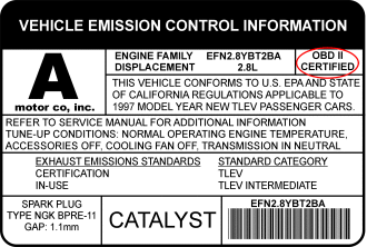
Freematics ONE+ plugs into the OBD port usually located under the steering column. To check if your vehicle is OBD-II certified, open your hood and find the sticker that looks like this:
Vehicles using following vehicle protocols are supported.
- CAN 500Kbps/29bit
- CAN 250Kbps/29bit
- CAN 500Kbps/11bit
- CAN 250Kbps/11bit
- KWP2000 Fast
- KWP2000 5Kbps
External I/O
Freematics ONE+ has an external I/O socket. The 4-pin socket contains 2x I/O pins (ESP32's GPIO26 and GPIO34), VCC (controllable by ESP32's GPIO12) and GND, as following.
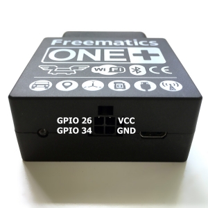
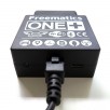
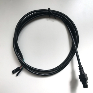
With a Molex to 2.54 Dupont connector conversion cable, external sensors or controller can be easily connected. On the Dupont connector side, black for GND, red for VCC, white for GPIO34 and green for GPIO26.
GNSS
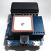
Freematics ONE+ Model B integrates u-blox M10 GNSS module and active ceramic antenna. The module is programmatically configurable while NMEA data stream is decoded by co-processor in real-time and coordinates made available to ESP32.
Bluetooth
Freematics ONE+ has built-in dual-mode Bluetooth capability and can work with Freematics Controller App via BLE when datalogger sketch or telelogger sketch uploaded.
Cellular Module
Freematics ONE+ Model B integrates SIM7670 LTE CAT-1 cellular module.
- Frequency Bands:
LTE-FDD:B1/B2/B3/B4/B5/B7/B8/B12/B13/B18/B19/B20/B25/B26/B28/B66/B71*
LTE-TDD:B34/B38/B39/B40/B41 - Data Transfer Speed:
10Mbps (Download) / 5Mbps (Upload)
SIM Card
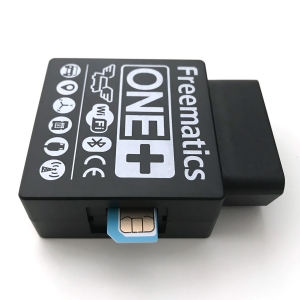
A microSIM card is needed for using cellular network and is inserted as shown below.
Global SIM cards like Hologram IoT SIM card are supported.
MicroSD
Freematics ONE+ has a microSD slot under the side cover which is connected to ESP32 via SPI. Standard Arduino SD library can be used for microSD card access.
Buzzer
The internal buzzer is connected to ESP32’s GPIO25 and can be driven by PWM or DAC.
Low-Power Mode
Freematics ONE+ enters and leaves low power mode programmatically. In low power mode with all peripherals (GPS, GSM, WIFI) powered off, the power consumption is around 10mA. This prevents car battery from going flat while the main controller is still able to run code and perform low-power tasks like motion detection by MEMS sensor.
Model Comparison
| Model B | Model A | |
|---|---|---|
| RAM Configuration | 520KB IRAM + 8MB PSRAM | 520KB IRAM |
| RTC | External 32K | Built-in (less accurate) |
| Cellular Module | Integrated 4G LTE module | Optional cellular module |
| GNSS | Integrated M8030 10Hz GNSS module and antenna | Via external GNSS receiver |
| External I/O | 2x GPIO for digital I/O, analog input, serial UART etc. | Occupied if GNSS receiver is connected |
| Co-Processor Features | Vehicle ECU interfacing GNSS data processing |
Vehicle ECU interfacing |
Development
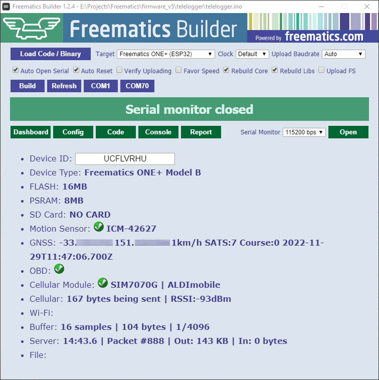
The most exciting thing about this product is that you can create your own unique product or solution on top of our massive accomplished work. We have been developing and maintaining a dedicated Arduino library for easy access to all hardware resources and a set of fully functional reference Arduino sketches for this product. So there is no need to start from scratch. As long as you have some basic knowledge about Arduino, you are good to go. Together with our Freematics Builder which allows configuring, compiling and uploading Arduino sketches in one simple GUI, we intend to bring the good out-of-box experience for non-professional developers. If you are a pro, we recommend PlatformIO IDE as development environment and our reference code is organized as PlatformIO projects as well, though you can still use Arduino IDE or Arduino makefile with ESP-IDF. For more information about development, please refer to the Developers Guide.
Shipping List
- Freematics ONE+ Model B x 1
- Micro USB cable x 1 (optional)
- External I/O cable x 1 (optional)
Links
Freematics Online Store © 2025

