Freematics ONE+ is based on ESP32 and can be programmed as an Arduino platform. We provide Arduino library and reference code for the hardware on which developers can evolve their own products with least efforts. If you are a pro, we highly recommend to use PlatformIO IDE or ESP-IDF as the development environment. For beginners, we provide a dedicated tool for configuring, compiling and uploading the code for a quick start.
Physical Interfaces
First of all, let’s get to know about the physical interfaces Freematics ONE+ has.
- OBD-II Male Connector (16-pin)
- GPIO Socket (4-pin)
- microSD card slot
- Micro SIM card slot (not used for units without cellular module)
- Micro USB Port
- LED Indicator
OBD-II Male Connector
OBD-II male connector allows Freematics ONE to be plugged directly into OBD-II female port which is available in most modern cars. The OBD-II port provides connection between Freematics ONE and car’s ECU computer as well as power supply from car battery.
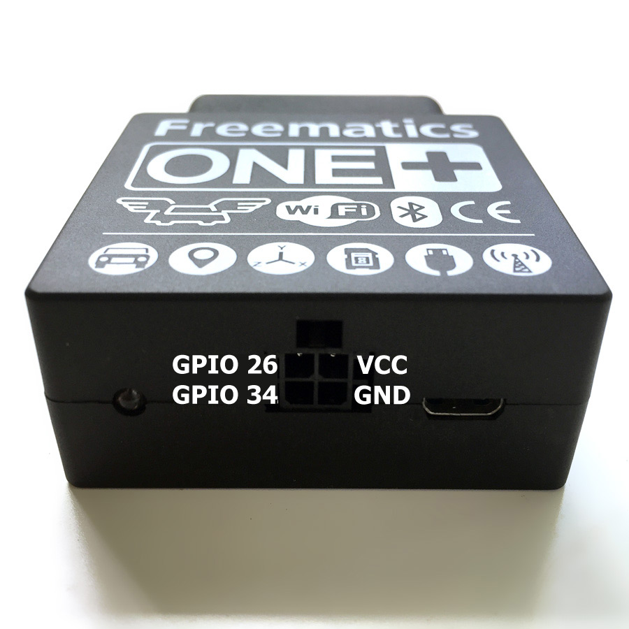
GPIO Socket
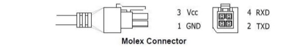
Freematics ONE+ has an external I/O socket on its enclosure. The 4-pin socket contains of 2x GPIO (from ESP32), VCC and GND. A 2.54 Molex connector is used for wiring. The line definition of the connector is as following.
- GND
- GPIO26 (ESP32)
- VCC (5V)
- GPIO34 (ESP32)
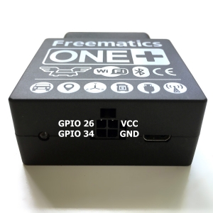
This socket allows connection of external GPS receivers which come as an optional accessory. The 4-pin connector is used for serial communication and also providing power for GPS receiver. Normally OBD-II port sits underneath dashboard where no good GPS signal reception is available. External GPS receiver with a cable led out from Freematics ONE can be easily placed on dashboard or somewhere else for better signal reception.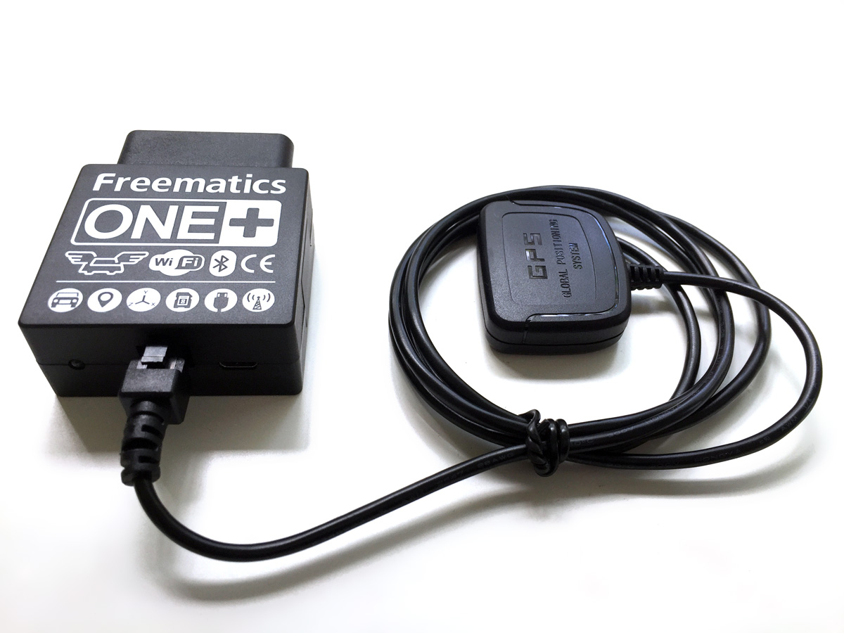
Card Slots
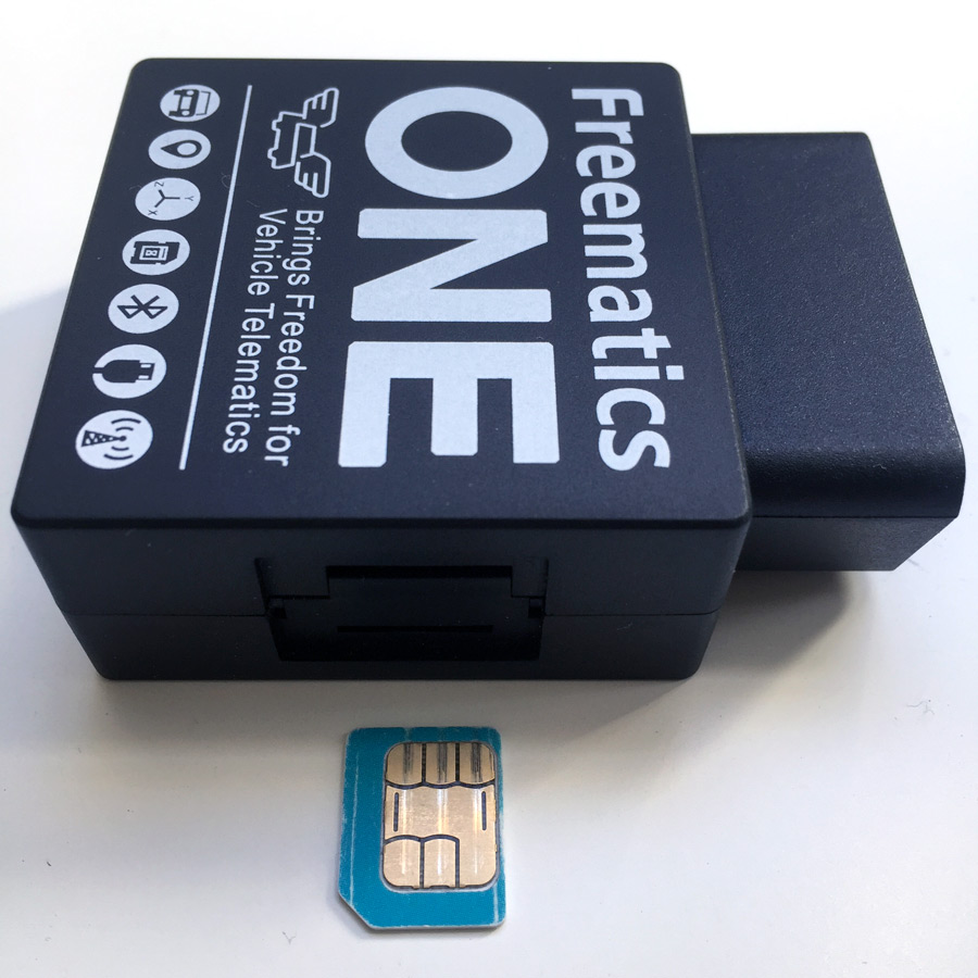
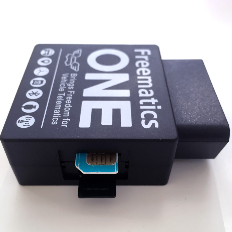
Freematics ONE has a microSD card slot and a micro SIM card slot under the plastic cover on one side of the enclosure. Both card seats are self-popping. Please avoid insert anything into SIM card slot if your Freematics ONE has no cellular module installed. Please make sure to insert microSD card and SIM card in the correct direction as shown below.

Micro USB Port
Micro USB port is for uploading Arduino sketch as well as serial communication. It can also be used for powering the device if the unit is not connected to OBD port. Please make sure enough current can be supplied. Using USB hub with external power supply is recommended.
Compiling and Uploading
Freematics ONE+ uses ESP32 as main controller. ESP32 has an actively developing Arduino core which makes it programmable as Arduino. Most important Arduino libraries like SPI, Wire and WiFi are well ported. There are a couple of ways to compile Arduino sketch for ESP32 and upload to it. Arduino IDE might be the most popular choice (setup guide here), however emerging modern IDEs are outperforming it in all aspects especially with better support for new Arduino variants.
Telelogger is one of the reference code for Freematics ONE+. It sets up peripherals and network, collects data from multiple sources including OBD, GNSS, motion sensor, and transmits the data to Freematics Hub or Traccar, via WiFi or cellular network, in UDP or HTTP protocol. The sketch and library for Freematics ONE+ are hosted on Github.
PlatformIO
The code of Telelogger can be loaded as a PlatformIO project. You need to install PlatformIO IDE which is built on top of Microsoft Visual Studio Code.
Once IDE installed, load the folder of telelogger and the project is ready for developing and compiling. The first loading may take a while as the ESP32 package is downloaded and installed on demand.
While waiting for the IDE to get ready, use USB cable to connect Freematics ONE+ to your computer’s USB port. PlatformIO will automatically detect serial port and normally you don’t need to alter it to start uploading.

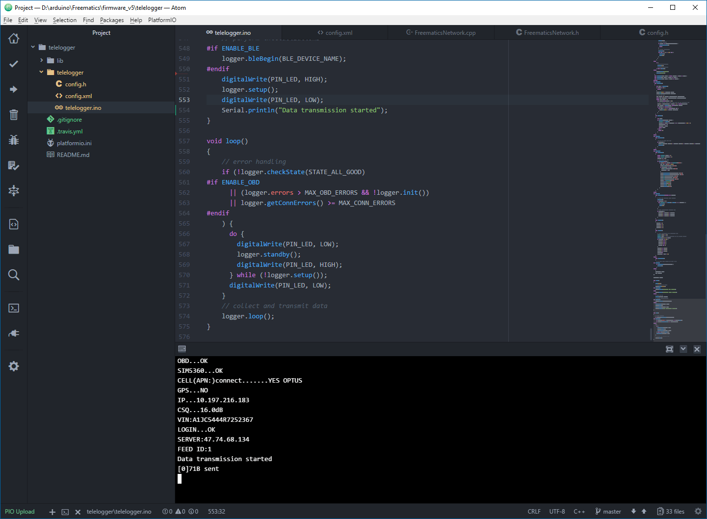
PlatformIO has built-in serial monitor. Once the uploading is done, and if Freematics ONE+ is in your car’s OBD-II port or you have a Freematics OBD-II Emulator which can be more convenient, you can open the serial terminal to monitor the working status from the serial output right away.
ESP-IDF
Telelogger ESP-IDF package integrates telelogger, Arduino library and ESP32 Arduino core and can be configured and built within ESP-IDF, ESP32’s software development environment, giving users full control over how firmware is built for Freematics ONE+.
A configuration page dedicated to telelogger is inserted in the configuration system.
To enter the configuration system, use following command from ESP-IDF command-line.
idf.py menuconfig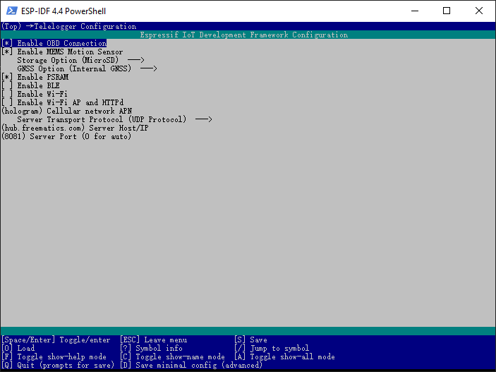
Once configured, complete firmware image can be built with following command.
idf.py buildIf successful, firmware can be uploaded to Freematics ONE+, running and serial output monitored with following command.
idf.py -p [serial port] flash monitor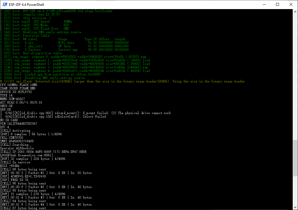
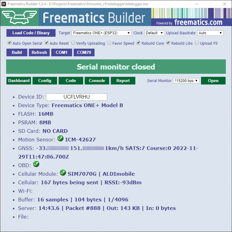
Freematics Builder
Freematics Builder is a self-contained utility for compiling and uploading Arduino sketch to Freematics products. It is especially handy for non-developers.