This guide helps you get started with Freematics ONE+ with least effort by using Freematics Arduino Builder. For information about developing with PlatformIO, refer to Developers Guide.
Physical Interfaces
First of all, let’s get to know about the physical interfaces Freematics ONE+ has.
- OBD-II Male Connector (16-pin)
- GPIO Socket (4-pin)
- microSD card slot
- Micro SIM card slot (not used for units without cellular module)
- Micro USB Port
- xBee Socket (inside)
- LED Indicator
OBD-II Male Connector
OBD-II male connector allows Freematics ONE to be plugged directly into OBD-II female port which is available in most modern cars. The OBD-II port provides connection between Freematics ONE and car’s ECU computer as well as power supply from car battery.
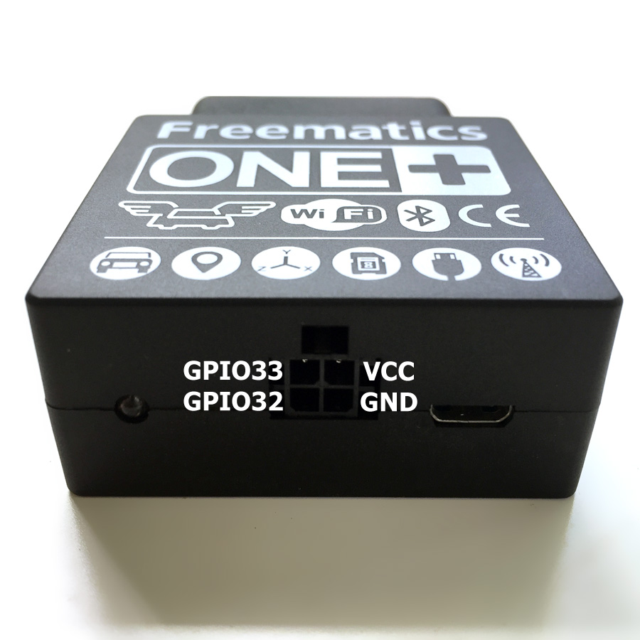
GPIO Socket
Freematics ONE+ has an external I/O socket on its enclosure. The 4-pin socket contains of 2x GPIO (from ESP32), VCC and GND. A 2.54 Molex connector is used for wiring. The line definition of the connector is as following.
- GND
- GPIO32 / Rx2 (ESP32)
- VCC (5V)
- GPIO33 / Tx2 (ESP32)

This socket allows connection of external GPS receivers which come as an optional accessory. The 4-pin connector is used for serial communication and also providing power for GPS receiver. Normally OBD-II port sits underneath dashboard where no good GPS signal reception is available. External GPS receiver with a cable led out from Freematics ONE can be easily placed on dashboard or somewhere else for better signal reception.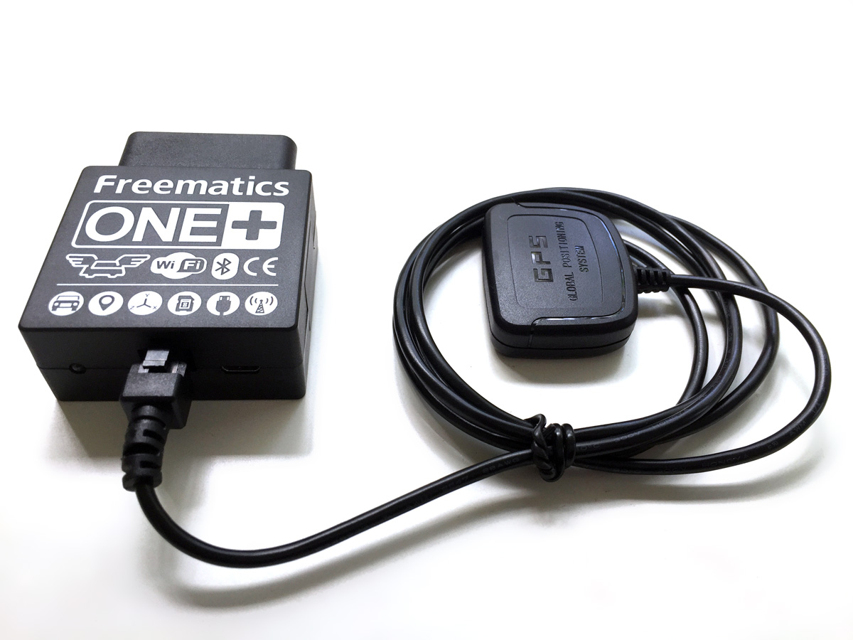
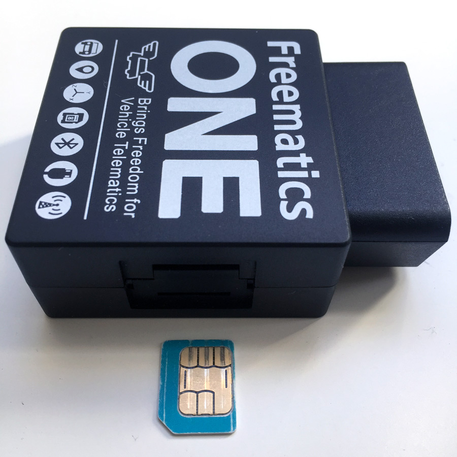
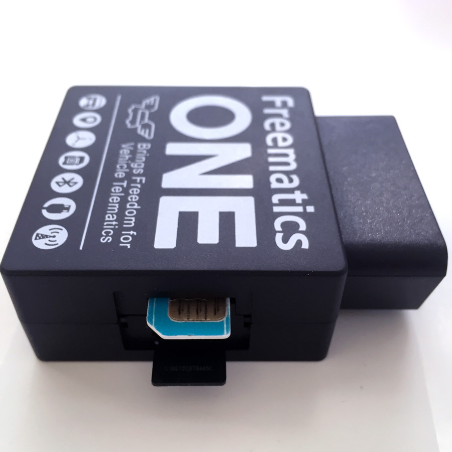
Card Slots
Freematics ONE has a microSD card slot and a micro SIM card slot under the plastic cover on one side of the enclosure. Both card seats are self-popping. Please avoid insert anything into SIM card slot if your Freematics ONE has no cellular module installed. Please make sure to insert microSD card and SIM card in the correct direction as shown below.

Micro USB Port
Micro USB port is for uploading Arduino sketch as well as serial communication. It can also be used for powering the device if the unit is not connected to OBD port. Please make sure enough current can be supplied. Using USB hub with external power supply is recommended.
Download Arduino library and sample sketches
Download the latest source code package from here or just clone the Github repository. Extract the downloaded package somewhere and you should see sketches and libraries in separate directories.
Install Freematics Arduino Builder
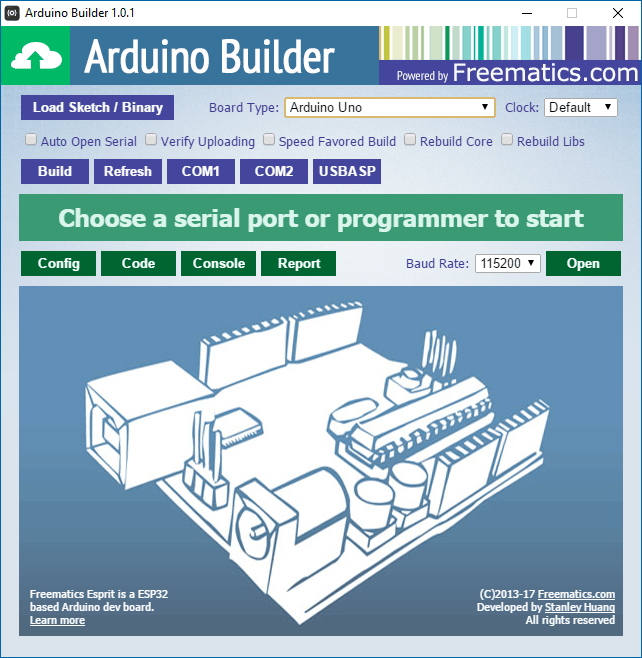
Freematics Arduino Builder is a quick tool for compiling Arduino sketch and uploading the compiled binary to Arduino board or Freematics ONE+ in this case. Basically you don’t need to do anything like environment setup or library import with it to compile the sketches you have just obtained. Simply download the installer and proceed with it. Once done, launch the program.
For development, it is recommended to use Arduino IDE or PlatformIO. Refer to Developers Guide for some related information. Please note that Freematics Arduino Builder is provided AS-IS and has no support or warranty from Freematics.
Connect Freematics ONE+ to computer
Connect Freematics ONE+ to your computer with USB cable. A serial port will appear just like an Arduino board. If not, download and install USB serial driver from here.
Using Freematics ONE+ as a vehicle data logger
Freematics ONE+ can work as a vehicle data logger which reads data from OBD-II, motion sensor and GPS (if present) and stores the data as files in the internal flash (SPIFFS) or on microSD card.
The data logger sketch is located in datalogger sub-directory. To use the sketch, click Load Sketch button and choose datalogger.ino. A configuration UI should come out like the following.
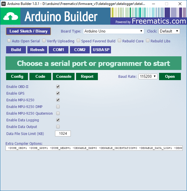
You can change options to enable or disable certain features provided by the sketch. Once done, click the serial port button corresponding to Freematics ONE+ to start compiling and uploading. If you are not sure which port to choose when there are more than one, disconnect the device, click Refresh button and see which one disappears and then connect again.
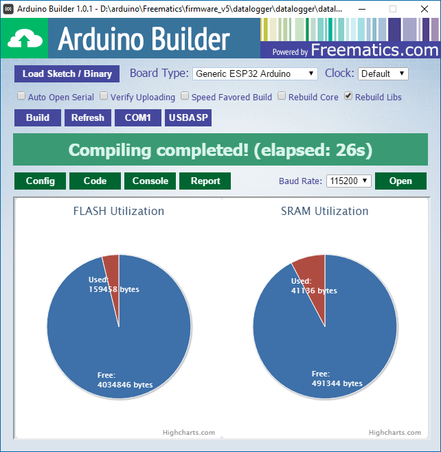
Once completed, you can click Open button to open the serial monitor to see the running result. The default baud rate is 115200bps. Normally you should have Freematics ONE+ connected to your car’s OBD-II port to see the sketch running.
Using Freematics ONE+ as a telemetry data logger over WIFI or cellular network
A telemetry data logger sketch is located in telelogger sub-directory. It reads data from OBD-II, motion sensor and GPS (if present), writes the data to files on microSD card (if card present) and send the data to a server overa WIFI or cellular network. We have developed and released Freematics Hub a free vehicle telemetry server software which works out-of-box with Freematics ONE+ running telelogger, capable of receiving, storing and illustrating real-time data transmitted from multiple devices.
If you don’t want to setup your own server but just want to test the device, you can use our server for testing.
Now load the sketch into Arduino Builder by clicking Load Sketch button and choose telelogger.ino. A configuration UI will come out as following.
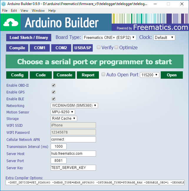
If you are going to use WIFI for Internet connection, change networking option to WIFI and change the SSID and password to that of your WIFI hotspot. If you are going to use cellular network (and you have cellular module in your Freematics ONE+ with SIM card inserted), change networking option to SIM800 (GPRS) or SIM5360 (WCDMA) according to what cellular module you have. It’s important to set the correct APN of your mobile network operator.
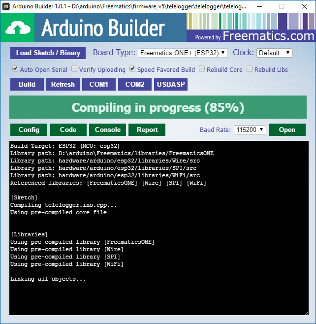
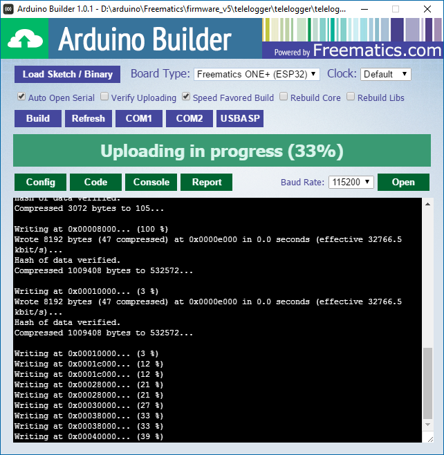
If you have setup Freematics Hub, change the Server Host to the actual domain name or IP address of the computer running Freematics Hub. If you don’t have a server setup yet, just leave it the default. If needed, change other options for enabling/disabling some features. Once all done, click the serial port button corresponding to Freematics ONE+ to start compiling and uploading.
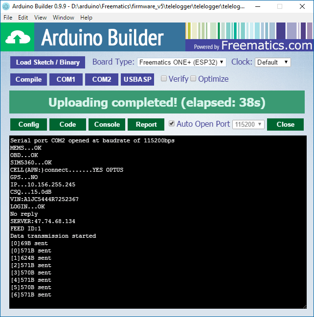
Once completed, you can click Open button to open the serial monitor to see the running result. You need to have Freematics ONE+ connected to your car’s OBD-II port and the number of bytes being sent will be displayed in serial monitor.
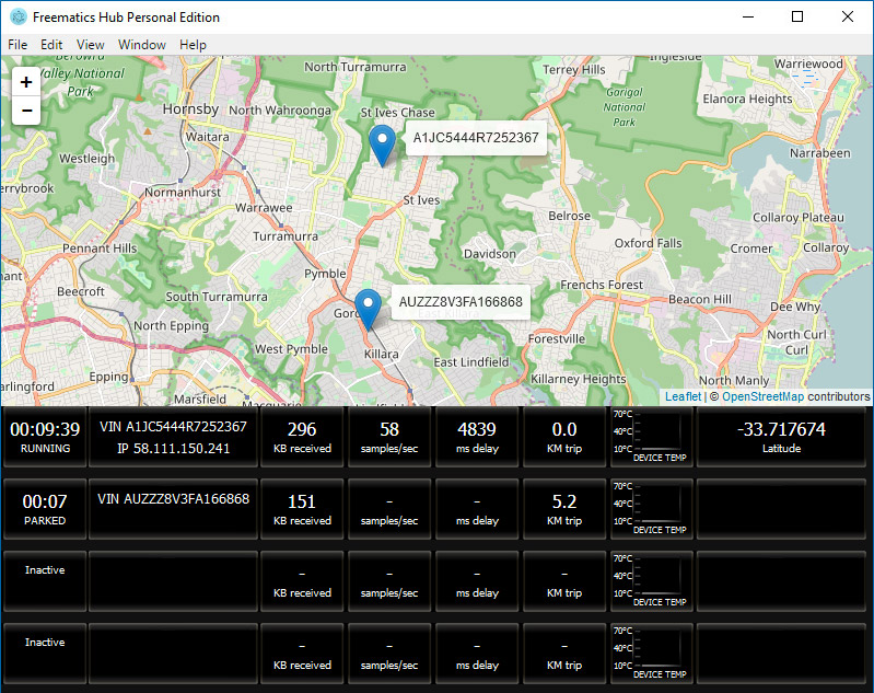
At this time, you will also see data showing up in Freematics Hub.
Troubleshooting
Unable to access OBD data
Please make sure the device is connected to a vehicle that uses one of supported vehicle data buses listed on the product page.
Unable to get GPS signal
Please make sure that the GPS receiver is exposed to open sky. There is normally very poor signal indoor even by the window.
Unable to connect to cellular network
Please make sure the cellular module is present and supports the band that your mobile network operator operates on. APN must be correctly set. Some operators may require APN password has specified.
Unable to upload code to device
This could happen when the device is not plugged in OBD port and is solely powered by USB cable. Some computer’s USB port can’t supply enough current surge and some long USB cable which has high resistance may also cause voltage to drop. It is recommended to plug the device into OBD port of real car or OBD simulator/emulator so it can be properly powered. For powering by USB only, it is recommended to use a USB hub with external power supply. Reducing upload baud rate would also help in most cases.