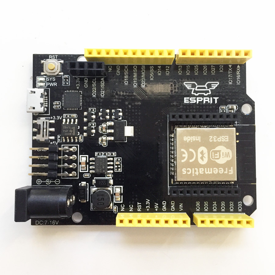
Freematics Esprit is an Arduino compatible development board based on Espressif ESP32 SoC designed for casual or serious IoT and telematics projects. The board leads out nearly all I/O pins from ESP32 into standard Arduino factor, making it familiar to Arduino players and also compatible with some existing Arduino shields.

Features
- Compatible with Arduino UNO pinouts
- Up to 240MHz clock frequency
- 520kB internal SRAM, 4MB internal Flash
- Integrated 802.11 BGN WiFi transceiver
- Integrated dual-mode Bluetooth (classic and BLE)
- Onboard xBee socket with switchable VCC voltage
- Additional I2C, 2x serial UART pinouts
Pinouts
Freematics Esprit leads out nearly all useful ESP32’s GPIO pins, arranged in a deliberated order, to balance between accessibility and Arduino compatibility.

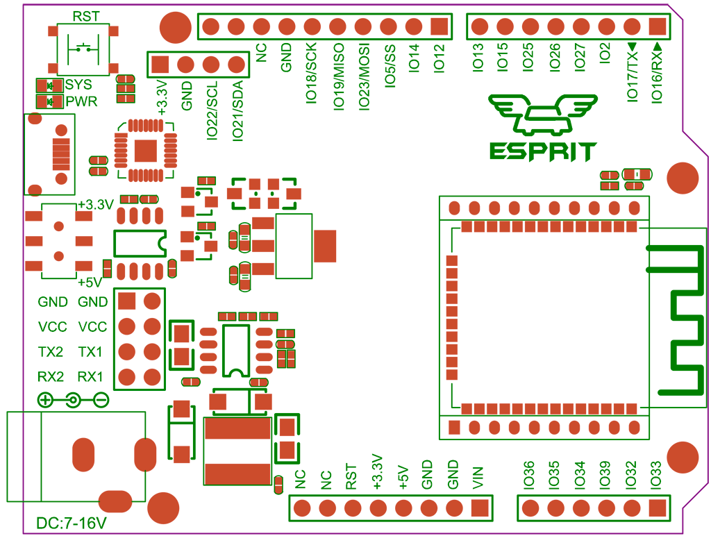
In addition to standard Arduino pin headers, following extra interfaces are available.
- 4-pin I2C header: SDA(GPIO21), SCL(GPIO22), 3.3v, GND
- 4-pin serial UART header #1: Rx(GPIO16), Tx(GPIO17), VCC (3.3V/5V), GND
- 4-pin serial UART header #2: Rx(GPIO32), Tx(GPIO33), VCC (3.3V/5V), GND
- xBee socket: Rx(GPIO32), Tx(GPIO33), VCC (3.3V/5V), GND
In fact, ESP32’s GPIO pins are fully configurable so the above additional pinouts are just for default/recommended usage and literally they can be remapped for any I/O purposes.
The VCC switch toggles between 3.3V and 5V for VCC pins of both serial UART header and xBee socket. The VCC/GND pins on UART header can be used to power the board, for example by Freematics OBD-II UART adapter.
The standard xBee socket VCC voltage is 3.3V, however, as we have released a series of cellular network bee modules which require 5V input, the switchable VCC makes the modules work on the board as well.
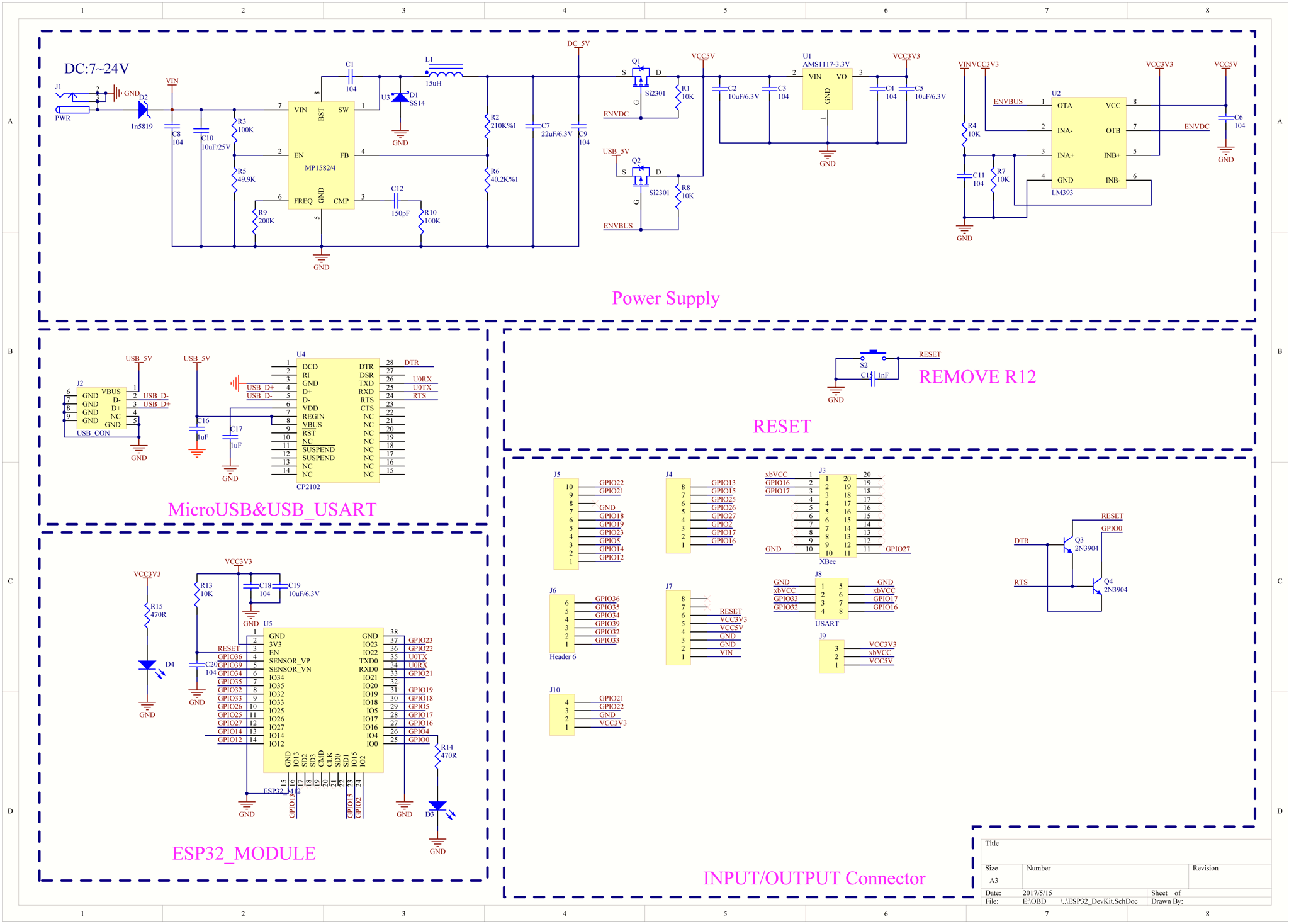
Schematic
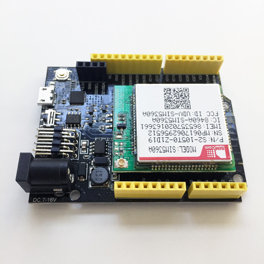
Cellular
Cellular module is attached to Freematics Esprit through the onboard xBee socket. Please be noted that xBee socket uses 5V VCC instead of normal 3.3V due to the efficiency consideration for powering cellular modules. Following chart compares the 3 types of cellular modules currently available.
| SIM800L | SIM5360E | SIM5360A | |
|---|---|---|---|
| GSM/GPRS | Quad-band 850/900/1800/1900MHz |
Quad-Band 850/900/1800/1900MHz |
Quad-Band 850/900/1800/1900MHz |
| GSM/EDGE | N/A | Quad-Band 850/900/1800/1900MHz |
Quad-Band 850/900/1800/1900MHz |
| UMTS/HSPA+ (WCDMA) |
N/A | Dual-Band 900/1900MHz |
Dual-Band 850/1900MHz |
| Power Consumption | 2W @ 850/900MHz 1W @ 1800/1900MHz |
0.25W @ UMTS 900/2100 2W @ GSM850/GSM900 1W @ DCS1800/PCS1900 |
0.25W @ UMTS 850/1900 2W @ GSM850/GSM900 1W @ DCS1800/PCS1900 |
| Popular Regions | Worldwide | Europe, Asia, Japan*, Australia* | US, Canada, Japan*, Australia* |
* Countries including Japan and Australia have both 3G bands in operation by different operators. Complete information is here.
Please note that xBee socket VCC needs to be switched to 5V when cellular module is attached.
Software
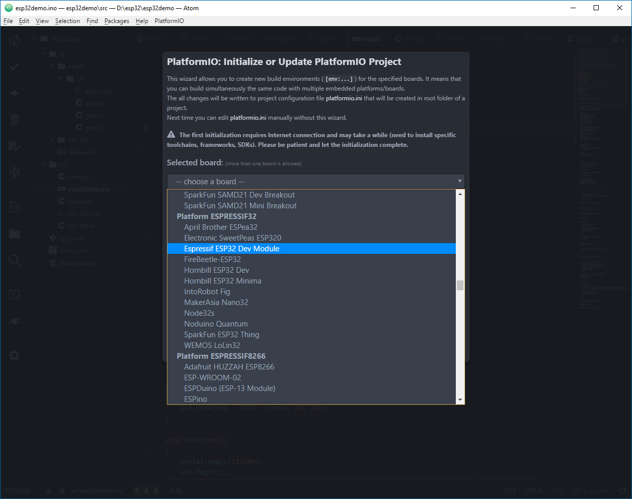
Freematics ESPRIT is ideal for programming with ESP32 Arduino core. When developing with Arduino IDE or Platform IO, please choose ESP32 Dev Module as board type. We hate to add another entry in the board type list as there are already too many literally same variants. To unleash more power from ESP32, we are currently developing a dedicated library for our board, so resources like BLE and CAN can be easily accessed from Arduino sketches.

As a bonus, our Freematics Arduino Builder has built-in support for compiling and uploading for Freematics Esprit.
Example Projects
OBD Data Display
This is a simple car data display made of Freematics Esprit with 1.3″ OLED display (SH1106 128×32 pixels) and Freematics OBD-II UART Adapter connected on Serial UART1 connector. It displays live car data obtained from OBD-II port.
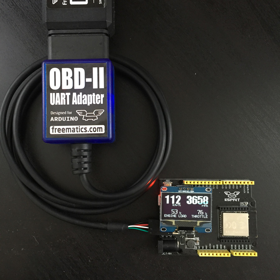
The Arduino sketch works on Freematics Esprit as well as common Arduino boards.
Check ESP32 Telematics Kit for more information.
Links
- Arduino Library
- Arduino Example Sketches
- ESP32 Arduino Core Github
- ESP32 SoC Datasheet
- Espressif ESP32 Resource Page
- Tutorial: Cellular network with SIM5360 on ESP32